Dave Armitage of Schaffner Group discusses the critical role EMI (electromagnetic interference) filtering has to play in electrical energy facilities.
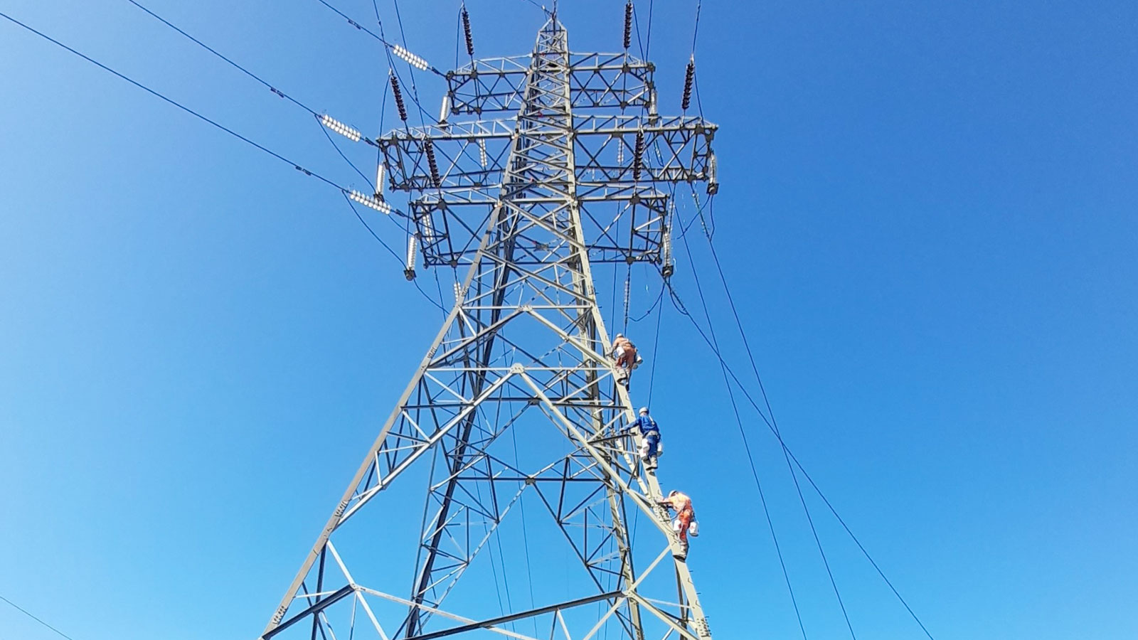
Today, electric utilities are facing an unprecedented challenge. There is, of course, the usual need for reliability, but also there is the increased demand to consider environmental issues and reducing carbon emissions. The reliable delivery of electric power to customers is the most obvious measure of how well a power grid is performing. The power grid cannot be susceptible to factors that can impact the reliability of power delivery.
Some of these factors result from electromagnetic interference (EMI). As defined in ANSI/IEEE Standard C63.14-2009, EMC is ‘the capability of electrical and electronic systems, equipment, and devices to operate in their intended electromagnetic environment within a defined margin of safety, and at design levels of performance without suffering or causing unacceptable degradation as a result of electromagnetic interference.’
So, for a device, equipment, or system to be compatible it must continue to operate as intended with any electromagnetic disturbances that may exist in its environment and, in addition, not create additional issues. Increased electromagnetic interference, or EMI, can adversely affect system efficiency and increase downtime by interfering with analogue control signals and industrial communications between devices/systems. So, as inter- and intra-communication networks expand, adequate electromagnetic compatibility or EMC design objectives need to be addressed.
The smart grid has the potential to improve the reliability of power delivery in many ways. But due to its increased complexity and reliance on RF/wireless technologies not previously incorporated into the grid, the smart grid EMC is directly related to electric power quality.
Many interference phenomena or disturbances can be related to power quality (i.e. power line harmonics, voltage surge, etc.) However, other than to recommend good installation and suppression practices, focusing on the immunity requirements needs to be compatible with the level of electrical magnetic disturbances anticipated. Smart grid devices (e.g. microprocessor-based systems, communications devices, plug-in electric vehicle chargers, etc.) can generate electromagnetic emissions that could cause interference to nearby electronic devices.
A growing number of customers are installing solar systems on their homes or businesses. In the United States alone, the installation of these solar systems continues to see a high annual growth rate. The power they’re injecting into distribution lines is causing voltage and frequency-control problems that threaten to destabilise the grid. While this is not yet a major problem, it could become one as distributed solar systems proliferate.
Detecting EMI can be difficult and time consuming at the system level as your facility project is completed, therefore, time and trouble can be saved if proper noise mitigation solutions are implemented into the design process.
For utility-scale (megawatt-sized) sources of wind energy, wind farms are established. Wind turbines are mounted on a tower to capture maximum energy. Several electricity providers today use wind farms to supply power to their customers. Simply stated, a wind turbine works the opposite of a fan; instead of using electricity to make wind, wind turbines use wind to make electricity. The energy in the wind turns two or three propeller-like blades around a rotor, the rotor is connected to the main shaft, which spins a generator to create electricity. Controllers in proximity to the generators and rotors can be prone to immunity issues.
The appropriate solution(s) can control the “flow” of electrical energy in and out of devices/systems and the appropriate physical infrastructure solution(s) can manage EMI issues between devices/systems. Control/signal cables placed in control panels can disrupt communications and control functions of an entire automated system and cause the failure of the installation.
Potential sources of EMI
Given the close proximity of sensitive devices to noisy sources, the leading modes of EMI are capacitive and inductive coupling amongst cabling and harnesses. Understanding this helps to examine how best practices and specifying noise mitigating products can improve the situation.
Generally, the noise coupling is unintentional and occurs when current flowing through one wire induces a voltage on a parallel wire. Capacitive coupling is more of a concern in high voltage circuits, while inductive coupling is more of a concern in high current circuits. To reduce or control this coupling, it’s typically recommended to keep a distance of three to six inches between high voltage and low voltage conductors that run in parallel to each other. Conductors that run perpendicular to each other are not subjected to the same levels of EMI. 12 inches is a typical distance between encoders.
There is a requirement for EMI filtering in electrical energy facilities or resolver feedback cables, motor or any AC power cable of any length which can, and usually will, act as an antenna. A simple rule of thumb is that the longer a wire is, the better an antenna it becomes.
Some common sources of noise can be categorised as follows:
1. Conducted noise from such sources as power line harmonics, surge (from lightning and power system switching transients), and fast transients/bursts (interruption of inductive DC circuits).
2. Radiated noise or signals from known transmitters (AM, FM, and TV broadcast transmitters, communications radios, wireless devices, etc.)
3. High power events such as geomagnetic storms, intentional EM interference (IEMI) from portable transmitters, and EM pulses associated with high altitude nuclear detonation (HEMP).
4. Electrostatic discharge events when a statically charged body (human or inert) comes into contact with a smart grid device.
The main source of noise in solar systems is the inverter, which is an electronic system that converts the direct current (DC) supplied by the photovoltaic (PV) panels into alternating current (AC) that flows on the power grid. The combination of smart inverters and new control methods will be essential to helping utilities transition to the grid of the future, in which vast amounts of wind- and solar-generated electricity will be the norm. This surge of power causes the voltage to spike. If the spike is high enough and lasts long enough, it can damage motors, generators, and distribution equipment.
Requirements
Presently, for most equipment, there is no regulatory mandate that a manufacturer’s product meet any immunity specification as immunity is considered a quality issue. Hence immunity considerations are left to the manufacturer and the purchaser to determine how much immunity is needed to work properly and to avoid recalls or in-field repairs. Thus, many electric utilities include specific requirements in their purchase specifications for equipment such as protective relays, power station and substation apparatus, and kilowatt-hour meters (including smart meters).
Components affected by EMI
There are many types of components that can be affected by EMI in power generating applications. These include analogue signals, measurement instrumentation, communication networks, and microprocessors.
Encoders rely on low-level signals from rotating machinery and can be especially susceptible to EMI. Symptoms include encoder counts changing with no motor rotation and non-repeatable position moves. Tachometers may show similar symptoms, such as incorrect speed readings and unexpected speed fluctuations. Sources of electrical noise near sensitive analogue signals and measurement instrumentation can often cause symptoms such as unexpected voltage spikes and ripple or jitter causing incorrect or non-repeatable readings.
With communication networks such as Ethernet links, electrical noise symptoms usually include loss of communication or errors in data. And with programmable logic controllers (PLCs) and other microprocessor-based components, symptoms can include not only loss of communications, but also faults or failure in the PLC or processor, unexpectedly triggering, and reporting of incorrect values.
What can we do?
Unfortunately, EMC is typically the last step in a design. When all the other product features have been implemented and the functionality is established, any EMC problems are then solved. At this point, EMC becomes expensive, time-consuming and difficult to handle. Manufacturers should therefore always start thinking about EMC in the early stages of product design. This thought process pertains to the EMI power input filter as well. Designers often forget that an EMI filter can assist not only with conducted emissions, but also in meeting immunity and fast transients requirements along with radiated emissions as well.
A power line or mains EMI filter is placed at the power entry point of the equipment that it is being installed into to prevent EM noise from exiting or entering the equipment. Lightning is a common event that effects local sections of the grid but can strike anywhere. The installation of proper grounding, surge protection, and equipment designed to tolerate moderate levels of electrical surges are all necessary to protect equipment against lightning events.
The design parameters for selecting an appropriate EMI filter include the attenuation or insertion loss, rated current, rated voltage, and regulatory approval requirements are specified by the user. However, there are many other parameters that should be or must be considered to get the most efficiency, reliability, and proper operation from the filter.