Andrew Baker, sales director North Europe, FLIR Systems Ltd, explores the role of thermal imaging when it comes to predicting substation failure.
The risk of blackouts and brownouts (a fall in voltage, typically causing lights to dim) are increasing on the power distribution grid due to ageing infrastructure and a lack of automation systems that monitor the condition of critical equipment at substations and elsewhere on the grid.
For example, transformer fluid leaks or internal insulation breakdown cause overheating that leads to failure, but many utilities don’t have automated thermal detection systems that reveal these problems.
Whatever the cause, a critical substation failure may cascade into a series of failures and impact massively on banking facilities, security systems, manufacturing plants, food refrigeration, communication networks and traffic control systems. Of course, the electric utility also stands to lose huge amounts of revenue and incur high costs in getting its systems up and running again.
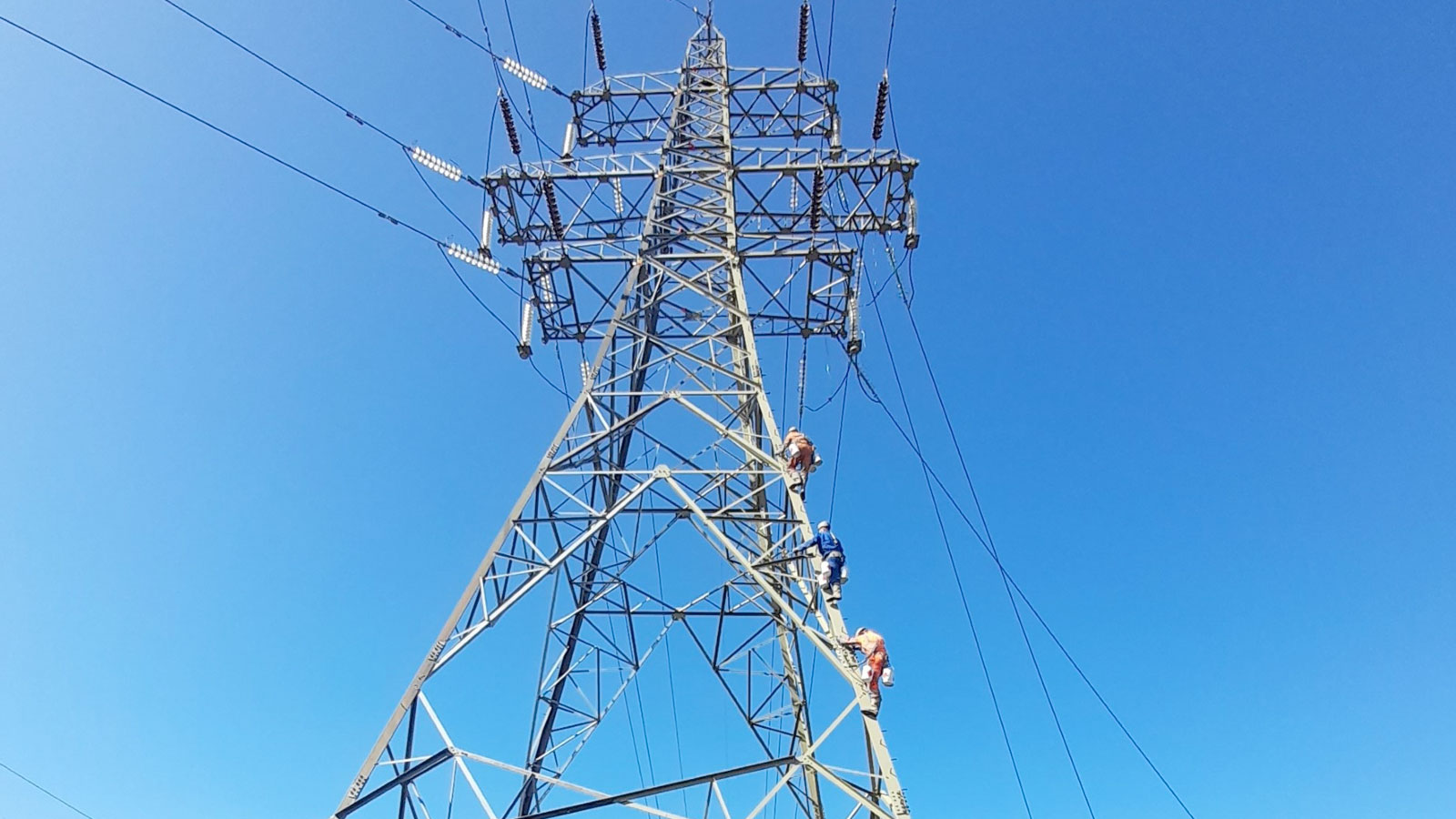
Although electric utilities have, for many years, used hand held thermal imaging cameras to monitor substation equipment, the adoption of permanently installed systems is relatively new, but certainly on the increase. These provide continuous early warning of impending equipment failures.
These systems employ advanced sensing and measurement technology control methods and digital communications. They anticipate, detect and respond rapidly to problems, thereby reducing maintenance costs, the chance of failure, a blackout and lost productivity.
An example; one large utility discovered a hot bushing rod in a substation transformer and repaired it at a cost of only £11,000. A similar problem that occurred before the company instituted its thermal imaging programme resulted in a catastrophic failure that cost more than two million pounds.
Typical substation components whose thermal signatures are precursors to failure include power transformers (oil levels and pump operation); load tap changers (oil levels, other internal problems); insulator bushings (oil levels and bad connections); stand-off insulators (moisture, contamination, degradation); lightning arrestors (degradation of metal oxide disks); circuit breakers (oil or SF6 leakage); mechanical disconnects (bad connections and contamination); control cabinets (wear and tear on fans, pumps and other components) and batteries.
What is thermal imaging?
The principle of thermal imaging is ‘many components heat up before they fail’. Secondly, all objects emit thermal radiation in the infrared spectrum that is not seen by the human eye.
Thermal imaging cameras convert that radiation into crisp images from which temperatures can be read. This non-contact temperature data can be displayed on a monitor in real-time and sent to a digital storage device for analysis.
The cameras do not require light to produce images and can see hot spots well before excessive heat or loss of insulation leads to failure. They can be mounted in all-weather housings and placed on pan/tilt drive mechanisms to survey large areas of a substation.
Differences in the heat signatures of electrical components and their surrounding background are recognised and compared to temperatures of similar components in close proximity.
Built-in logic, memory and data communications allow the cameras to evaluate the temperatures in the images with user-defined settings and send that data to a central monitoring station for trend analysis, alarm triggering and the generation of reports. The devices can even notify managers in remote locations of abnormal conditions by sending an email.
Typical system configuration
In co-operation with automation system suppliers, a quality camera manufacturer can create customised thermal imaging and non-contact temperature measurement systems for substations. They can automatically perform site patrols and monitor equipment temperatures without human supervision. The video images and their temperature data are carried over Ethernet, wireless or over fibre optic cables to an appropriate interface that communicates this data to the central monitoring location.